聊城 网站制作怎么制作个人网站
需求:
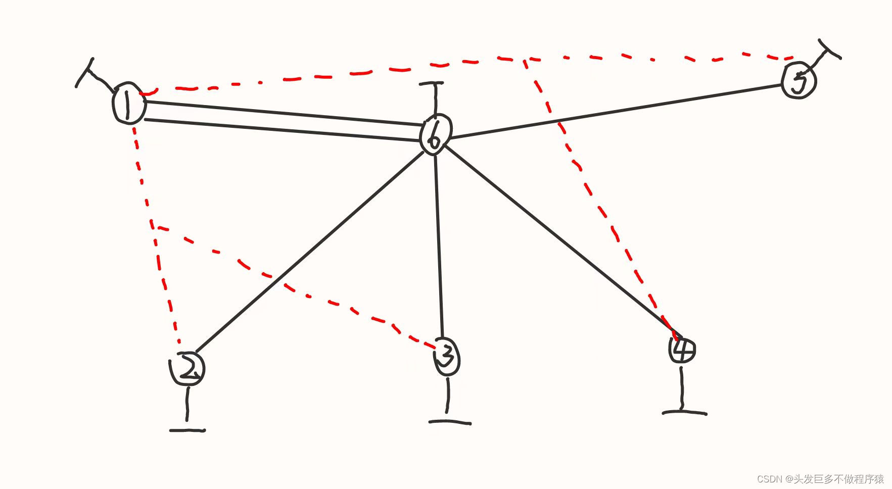
1、R6为ISP只能配置IP地址,R1-R5的环回为私有网段。
2、R1/4/5为全连的MGRE结构,R1/2/3为星型的拓扑结构,R1为中心站点。
3、所有私有的网段可以互相通讯,私有网段使用OSPF协议完成。
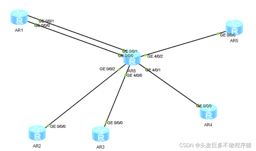
第一步、搭建拓扑并按如图配置IP地址。
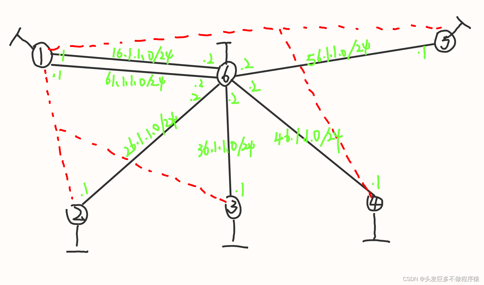
第二步、写缺省路由和nat策略
[AR1]ip route-static 0.0.0.0 0 61.1.1.2
[AR1]ip route-static 0.0.0.0 0 16.1.1.2
[AR1]acl 2000
[AR1-acl-basic-2000]rule permit source 1.1.1.1 0.0.0.0
[AR1-acl-basic-2000]q
[AR1]interface g0/0/0
[AR1-GigabitEthernet0/0/0]nat outbound 2000
[AR1-GigabitEthernet0/0/0]q
[AR1]interface g0/0/1
[AR1-GigabitEthernet0/0/1]nat outbound 2000
[AR1-GigabitEthernet0/0/1]q[AR2]ip route-static 0.0.0.0 0 26.1.1.2
[AR2]acl 2000
[AR2-acl-basic-2000]rule permit source 2.2.2.0 0.0.0.255
[AR2-acl-basic-2000]q
[AR2]interface g0/0/0
[AR2-GigabitEthernet0/0/0]nat outbound 2000
[AR2-GigabitEthernet0/0/0]q[AR3]ip route-static 0.0.0.0 0 36.1.1.2
[AR3]acl 2000
[AR3-acl-basic-2000]rule permit source 3.3.3.3 0.0.0.0
[AR3-acl-basic-2000]q
[AR3]interface g0/0/0
[AR3-GigabitEthernet0/0/0]nat outbound 2000
[AR3-GigabitEthernet0/0/0]q[AR4]ip route-static 0.0.0.0 0 46.1.1.2
[AR4]acl 2000
[AR4-acl-basic-2000]rule permit source 4.4.4.4 0.0.0.0
[AR4-acl-basic-2000]q
[AR4]interface g0/0/0
[AR4-GigabitEthernet0/0/0]nat outbound 2000
[AR4-GigabitEthernet0/0/0]q[AR5]ip route-static 0.0.0.0 0 56.1.1.2
[AR5]acl 2000
[AR5-acl-basic-2000]rule permit source 5.5.5.5 0.0.0.0
[AR5-acl-basic-2000]q
[AR5]interface g0/0/0
[AR5-GigabitEthernet0/0/0]nat outbound 2000
[AR5-GigabitEthernet0/0/0]q
第三步、启用MGRE并按照下图配置IP地址。
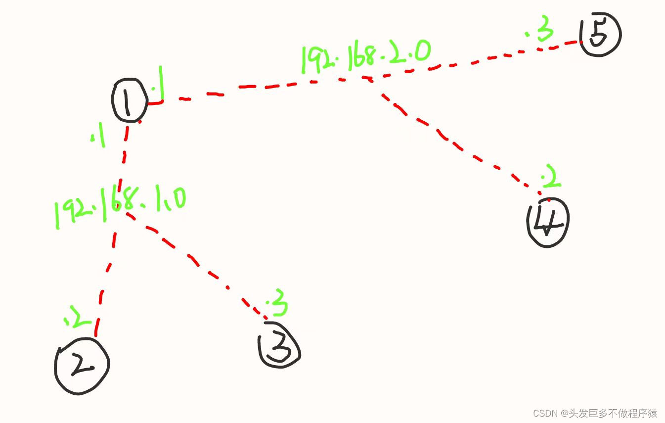
[AR1]interface Tunnel 0/0/0
[AR1-Tunnel0/0/0]ip address 192.168.1.1 24
[AR1-Tunnel0/0/0]tunnel-protocol gre p2mp
[AR1-Tunnel0/0/0]source 61.1.1.1
May  4 2024 17:08:59-08:00 AR1 %%01IFNET/4/LINK_STATE(l)[4]:The line protocol IP on the interface Tunnel0/0/0 has entered the UP state.
[AR1-Tunnel0/0/0]nhrp entry multicast dynamic
[AR1-Tunnel0/0/0]nhrp network-id 100[AR2]interface Tunnel 0/0/0
[AR2-Tunnel0/0/0]ip address 192.168.1.2 24
[AR2-Tunnel0/0/0]tunnel-protocol gre p2mp
[AR2-Tunnel0/0/0]source GigabitEthernet 0/0/0
May  4 2024 17:12:19-08:00 AR2 %%01IFNET/4/LINK_STATE(l)[0]:The line protocol IP on the interface Tunnel0/0/0 has entered the UP state.
[AR2-Tunnel0/0/0]nhrp entry 192.168.1.1 61.1.1.1 re
[AR2-Tunnel0/0/0]nhrp entry 192.168.1.1 61.1.1.1 register
[AR2-Tunnel0/0/0]nhrp network-id 100[AR3]interface Tunnel 0/0/0
[AR3-Tunnel0/0/0]ip address 192.168.1.3 24
[AR3-Tunnel0/0/0]tunnel-protocol gre p2mp
[AR3-Tunnel0/0/0]source GigabitEthernet 0/0/0
May  4 2024 17:14:43-08:00 AR3 %%01IFNET/4/LINK_STATE(l)[0]:The line protocol IP on the interface Tunnel0/0/0 has entered the UP state.
[AR3-Tunnel0/0/0]nhrp entry 192.168.1.1 61.1.1.1 register
[AR3-Tunnel0/0/0]nhrp network-id 100[AR1]interface Tunnel 0/0/1
[AR1-Tunnel0/0/1]ip address 192.168.2.1 24
[AR1-Tunnel0/0/1]tunnel-protocol gre p2mp
[AR1-Tunnel0/0/1]source 16.1.1.1
May  4 2024 17:40:17-08:00 AR1 %%01IFNET/4/LINK_STATE(l)[0]:The line protocol IP on the interface Tunnel0/0/1 has entered the UP state.
[AR1-Tunnel0/0/1]nhrp entry multicast dynamic
[AR1-Tunnel0/0/1]nhrp network-id 200
[AR1-Tunnel0/0/1]q[AR4]interface Tunnel 0/0/0
[AR4-Tunnel0/0/0]ip address 192.168.2.2 24
[AR4-Tunnel0/0/0]tunnel-protocol gre p2mp
[AR4-Tunnel0/0/0]source 46.1.1.1
May  4 2024 17:42:33-08:00 AR4 %%01IFNET/4/LINK_STATE(l)[0]:The line protocol IP on the interface Tunnel0/0/0 has entered the UP state.
[AR4-Tunnel0/0/0]nhrp entry 192.168.2.1 16.1.1.1 register
[AR4-Tunnel0/0/0]nhrp network-id 200
[AR4-Tunnel0/0/0]q[AR5]interface Tunnel 0/0/0
[AR5-Tunnel0/0/0]ip address 192.168.2.3 24
[AR5-Tunnel0/0/0]tunnel-protocol gre p2mp
[AR5-Tunnel0/0/0]source 56.1.1.1
May  4 2024 17:44:29-08:00 AR5 %%01IFNET/4/LINK_STATE(l)[0]:The line protocol IP on the interface Tunnel0/0/0 has entered the UP state.
[AR5-Tunnel0/0/0]nhrp entry 192.168.2.1 16.1.1.1 register
[AR5-Tunnel0/0/0]nhrp network-id 200
[AR5-Tunnel0/0/0]q
第四步、启用OSPF协议。
[AR1]ospf 1 router-id 1.1.1.1
[AR1-ospf-1]area 0
[AR1-ospf-1-area-0.0.0.0]network 192.168.1.0 0.0.0.255
[AR1-ospf-1-area-0.0.0.0]network 1.1.1.1 0.0.0.0
[AR1-ospf-1-area-0.0.0.0]network 192.168.2.0 0.0.0.255
[AR1-ospf-1-area-0.0.0.0]q
[AR1-ospf-1]q[AR2]ospf 1 router-id 2.2.2.2
[AR2-ospf-1]area 0
[AR2-ospf-1-area-0.0.0.0]network 192.168.1.0 0.0.0.255
[AR2-ospf-1-area-0.0.0.0]network 2.2.2.2 0.0.0.0[AR3]ospf 1 router-id 3.3.3.3
[AR3-ospf-1]area 0
[AR3-ospf-1-area-0.0.0.0]network 192.168.1.0 0.0.0.255
[AR3-ospf-1-area-0.0.0.0]network 3.3.3.3 0.0.0.0
[AR3-ospf-1-area-0.0.0.0]q
[AR3-ospf-1]q[AR4]ospf 1 router-id 4.4.4.4
[AR4-ospf-1]area 0
[AR4-ospf-1-area-0.0.0.0]network 192.168.2.0 0.0.0.255
[AR4-ospf-1-area-0.0.0.0]network 4.4.4.4 0.0.0.0[AR5]ospf 1 router-id 5.5.5.5
[AR5-ospf-1]area 0
[AR5-ospf-1-area-0.0.0.0]network 192.168.2.0 0.0.0.255
[AR5-ospf-1-area-0.0.0.0]network 5.5.5.5 0.0.0.0
第五步、修改接口类型并修改优先级
[AR1]interface Tunnel 0/0/0
[AR1-Tunnel0/0/0]ospf network-type broadcast
[AR1]interface Tunnel 0/0/1
[AR1-Tunnel0/0/1]ospf network-type broadcast[AR2]interface Tunnel 0/0/0
[AR2-Tunnel0/0/0]ospf network-type broadcast
[AR2-Tunnel0/0/0]ospf dr-priority 0[AR3]interface Tunnel 0/0/0
[AR3-Tunnel0/0/0]ospf network-type broadcast
[AR3-Tunnel0/0/0]ospf dr-priority 0[AR4]interface Tunnel 0/0/0
[AR4-Tunnel0/0/0]ospf network-type broadcast
[AR4-Tunnel0/0/0]ospf dr-priority 0[AR5]interface Tunnel 0/0/0
[AR5-Tunnel0/0/0]ospf network-type broadcast
[AR5-Tunnel0/0/0]ospf dr-priority 0
实验完成